-
Building E, No. 65 Xingshan North Road, Liangtian, Baisha Industrial Park, Baiyun District, Guangzhou
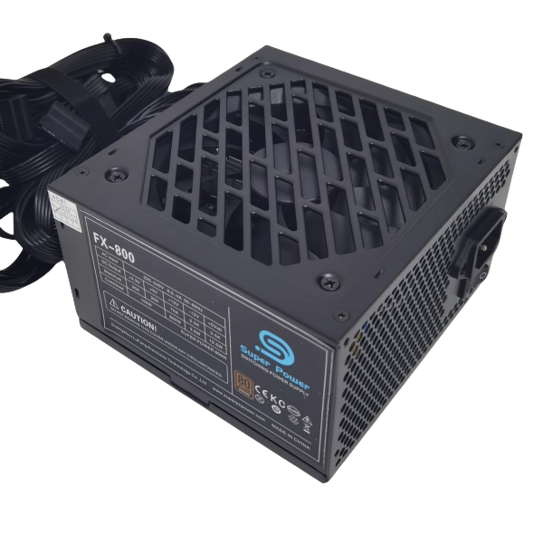
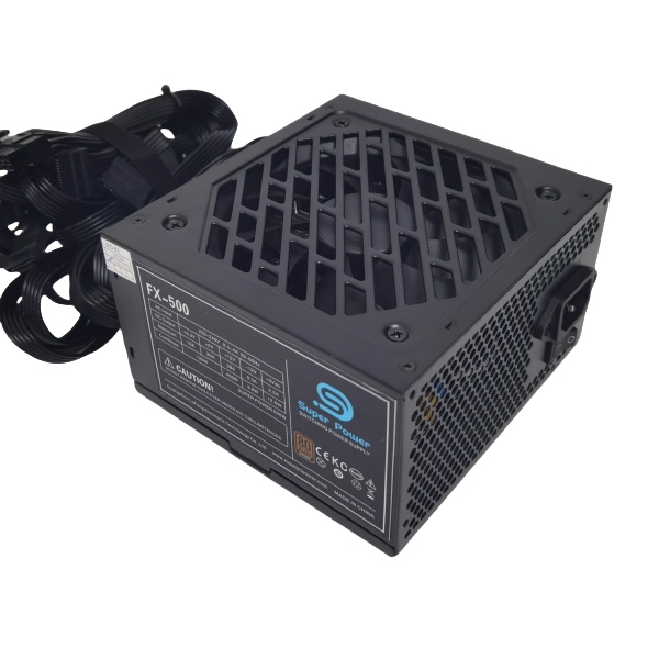
9 Steps to Producing a Benchtop Power Supply
The production process of a desktop power supply (PC Power Supply Unit, PSU) involves multiple links, covering electronic component assembly, circuit design, safety testing, etc. The following is 9 steps to producing a benchtop power supply:
1. Design and development
Circuit design:
The design and development of desktop power supplies is the starting point of the production process and directly determines the performance, efficiency and reliability of the product. First, engineers need to define the input and output parameters of the power supply according to industry standards (such as Intel ATX specifications), including rated power (such as 500W, 750W), voltage range (+12V, +5V, +3.3V, etc.) and interface type (24pin motherboard power supply, PCIe 8pin, etc.). The core circuit design usually adopts the “active PFC+LLC resonance+synchronous rectification” architecture to achieve high conversion efficiency (such as 80 PLUS gold medal or above). At this stage, the stability of the topology structure needs to be verified through simulation software (such as SPICE) to ensure that the voltage can remain stable under extreme conditions such as load mutation and high temperature.
Component selection: Select key components (such as capacitors, inductors, MOSFETs, transformers, heat sinks, etc.), considering efficiency (such as 80 PLUS certification), power density and cost.
Simulation verification:
In terms of component selection, key components need to take into account both performance and cost: the main control chip is mostly Taiwanese (such as Great Wall) or American (such as Texas Instruments) solutions; capacitors need to meet high temperature resistance (above 105°C) and long life (such as Japanese Nippon Chemi-Con); and cooling fans need to balance noise (<25dB) and air volume. In addition, the design team needs to optimize the PCB layout, such as isolating the high-voltage area (primary side) from the low-voltage area (secondary side), reducing electromagnetic interference (EMI), and reducing impedance and heat loss through multi-layer wiring.
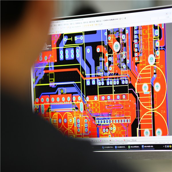
PCB layout:
The design stage also needs to predict certification requirements (such as UL, CE, FCC) to avoid EMI exceeding the standard or insulation failure risks in advance. For example, safety distances (creepage distances and electrical clearances) must comply with the IEC 60950 standard, and the PFC circuit must meet the IEC 61000-3-2 harmonic limits. Finally, the design documents (including circuit diagrams, BOM lists, and 3D structural models) will be transferred to the production stage to provide precise guidance for subsequent material procurement and assembly. This process usually takes several months to half a year and is the foundation of power quality.
2. Raw material procurement and inspection
Raw material procurement and inspection are crucial links in PC power supply production, which directly affect product quality and reliability. In terms of component procurement, we strictly control the quality of key components, such as electrolytic capacitors, PFC inductors, main transformers, IC control chips, and fans, which are the core of power supply performance. The raw materials we purchase must comply with RoHS environmental standards to ensure the environmental protection and sustainability of the products.
Incoming material inspection (IQC) is the key to ensure that all components entering the production line meet the quality standards. We conduct comprehensive quality inspections on components, including the capacity and withstand voltage of capacitors, the on-resistance of MOSFETs, and other key parameters to ensure that they fully meet the design requirements. Our IQC process is rigorous and meticulous, and each batch of raw materials is strictly tested to prevent any unqualified components from entering the production process, thereby ensuring the excellent quality and long-term reliability of the final product. This helps us guarantee product quality and provide better services.
3. PCB production
PCB (Printed Circuit Board) production is the core link of PC power supply manufacturing. It provides reliable connection and support for electronic components, just like the “skeleton” of power supply. Our PCB production process strictly follows industry standards to ensure that each PCB has excellent performance and durability.
Substrate production:
We select high-quality insulating substrates, such as FR-4 or higher grade materials, which have excellent electrical insulation properties and mechanical strength. Copper foil is laminated to the insulating substrate to form a PCB substrate. The thickness of the copper foil is usually between 1 ounce (about 35 microns) or 2 ounces (about 70 microns), and the specific choice depends on the design current and voltage level of the power supply.
Photolithography and etching:
We use photolithography to transfer the circuit pattern to the PCB substrate. This is similar to the process of developing a photo, in which the photosensitive material is exposed according to the circuit diagram. Through etching, we remove the excess copper layer, leaving the required circuit traces and pads, thus forming the “blood vessel” system of the power supply. Etching accuracy can usually reach 0.1mm or less to meet the needs of high-density circuit design.
Drilling and copper deposition:
It is a key step in PCB production. We use high-precision drilling equipment to drill through holes (vias) and component pin holes on PCBs. Through holes are used to connect different layers of PCBs and provide channels for the transmission of current. The copper plating process is to plate a layer of copper on the wall of the drilled hole to ensure the conductivity of the through hole. The control of hole size and spacing is crucial to the electrical performance of the PCB. For example, the diameter of the through hole is usually between 0.3mm and 0.6mm to meet the needs of current transmission.
Solder mask and silk screen:
We apply solder mask ink, usually green or other colors, on the surface of the PCB to protect the circuit traces from corrosion and short circuits. The solder mask is also used to define the soldering area of the component. Next, we print component identification on the PCB, such as the number of resistors and capacitors, to facilitate subsequent component assembly and maintenance. The thickness of the solder mask is generally between 15 microns and 30 microns to ensure good protection of the circuit. After these rigorous processes, each PCB will achieve optimal performance.
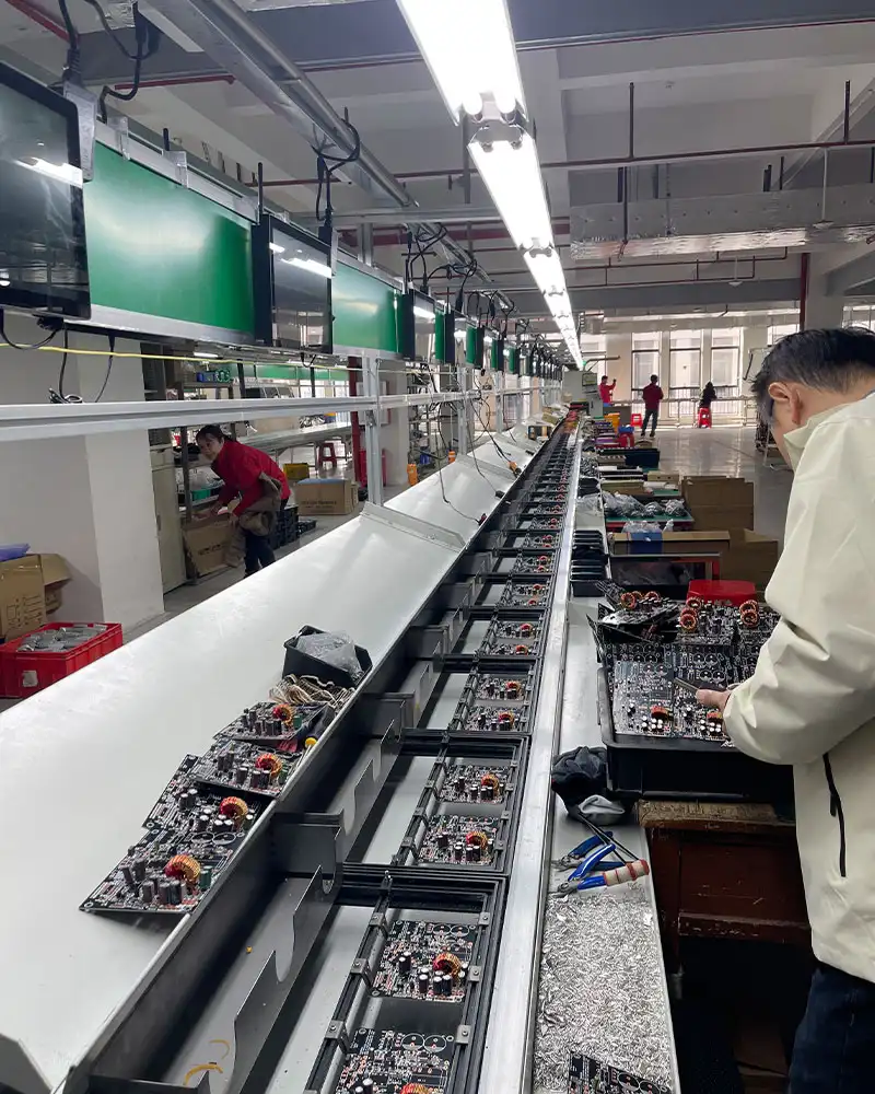
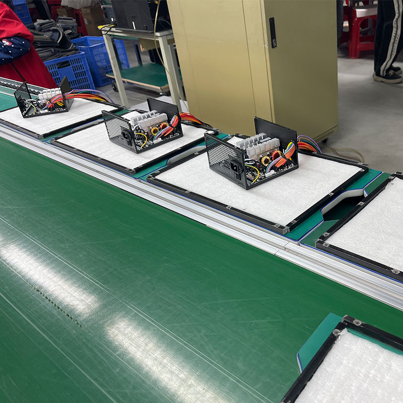
4. Component installation
It is a key step in PC power supply assembly. It connects the “skeleton” on the PCB with various electronic components to form the “heart” of the power supply. Our component installation process uses advanced SMT (surface mount technology) and traditional plug-in technology to ensure accurate installation and reliable connection of components.
SMT patch:
With the help of high-precision patch machines, we accurately solder small components such as resistors, capacitors, IC chips, etc. to the pads of the PCB. The patch machine can achieve high-speed and high-precision patching, and the patch accuracy can usually reach 0.1mm. Then, we use the reflow soldering process to melt the solder paste so that the components are firmly fixed on the PCB. The temperature curve of reflow soldering is precisely controlled to ensure the quality of welding.
Component installation:
It is for large-size components, such as electrolytic capacitors, transformers, and heat sink pins. These components are usually large in size and cannot be patched by SMT. Our workers insert these components into the corresponding holes of the PCB manually or by machine during the plug-in process. Manual plug-in ensures flexibility and precision of installation, while machine plug-in improves efficiency and consistency.
Wave soldering:
soldering plug-in components to form reliable electrical connections. Wave soldering is to immerse the PCB in molten solder so that the solder wets the component pins and forms solder joints. The temperature and time of wave soldering are precisely controlled to ensure soldering quality. Through these rigorous processes, each power supply is assembled to optimal performance.
5. Key module assembly
It is the core link of PC power supply manufacturing. These modules directly determine the performance, efficiency and reliability of the power supply. We use precise processes and strict quality control in the assembly of key modules to ensure that each module can achieve optimal performance.
PFC (Power Factor Correction) Module:
We will install active or passive power factor correction circuits to improve power utilization. Active PFC circuits can significantly improve the power factor of the power supply to close to 1, thereby reducing reactive power losses in the power grid and meeting energy efficiency standards. We will ensure the quality and installation of key components such as PFC inductors to ensure the performance of PFC modules.
Main Transformer and Rectifier Module:
We will assemble high-frequency transformers to isolate AC power and adjust the voltage. The quality and design of the transformer are crucial to the efficiency and stability of the power supply. At the same time, we will also assemble rectification circuits, such as synchronous rectification or Schottky diodes. These components are used to convert AC power to DC power to provide the required voltage for various components of the computer. The correct selection and installation of these components are crucial to the output quality of the power supply.
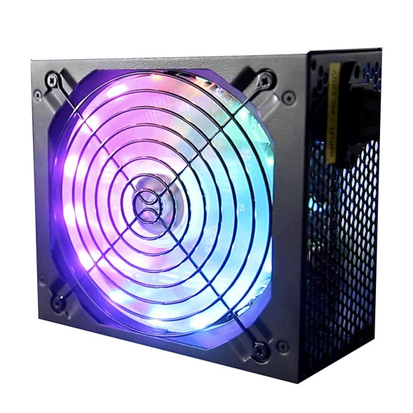
Cooling System:
Since the power supply generates heat during operation, the cooling system is crucial. We will fix the heat sink, usually made of aluminum alloy, to increase the heat dissipation area. We will also apply thermal conductive silicone to enhance the heat conduction between the heat sink and the heating element. In addition, we will install a cooling fan, usually a 12cm or 14cm fan, to provide effective air circulation, remove heat from the inside of the power supply, and keep the power supply running stably.
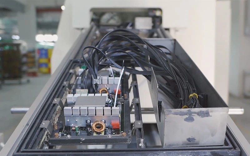
6. Power module assembly
It is the last process of PC power supply manufacturing, which integrates all internal components together to form a complete and usable power supply. In this link, we pay attention to every detail to ensure the safety, stability and beauty of the power supply.
Casing assembly:
We install internal components such as PCB (printed circuit board), fan, switch, etc. into the metal casing, which is usually made of galvanized steel plate to provide solid protection and good EMI (electromagnetic interference) shielding effect. EMI shielding can effectively prevent electromagnetic radiation inside the power supply from interfering with other electronic devices and reduce the impact of external electromagnetic interference on the power supply. During the casing assembly process, we ensure that all components are firmly fixed in the casing and tightly connected to the casing.
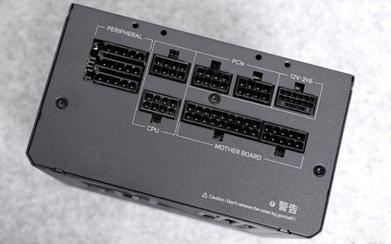
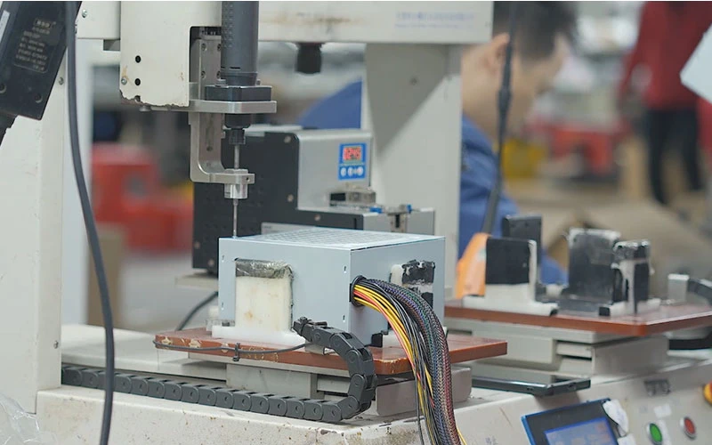
Cable welding:
We will connect various output cables, including 24pin motherboard power supply, PCIe power supply, SATA power supply, etc., which are used to provide power to various components of the computer. The quality of welding is directly related to the stability and reliability of the power supply. We use high-quality welding materials and processes to ensure that the welding points are firm and reliable. After welding, we will put insulating sleeves on the cables to prevent short circuits and other safety hazards.
Fixing and Insulation:
We use screws to fix the internal components to prevent them from moving or loosening during transportation or use. To further improve the safety of the power supply, we also add insulating sheets or rubber pads to prevent short circuits between internal components. The material and thickness of the insulating sheet are carefully selected to ensure good insulation. Through these processes, each power module will achieve a safe, stable and reliable effect.
7. Testing and calibration
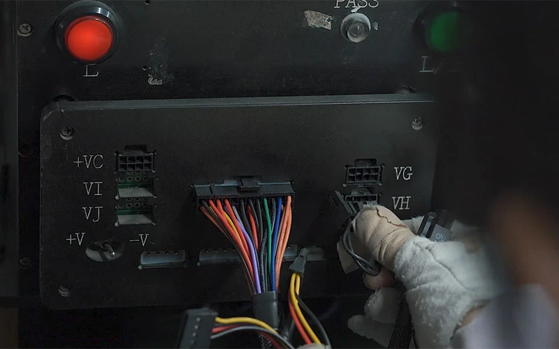
Power-on test:
Check whether the no-load voltage and standby power supply (+5VSB) are normal.
Load test: simulate full-load operation to verify the stability of each voltage output (+12V, +5V, +3.3V).
Protection function test:
trigger overvoltage protection (OVP), overcurrent protection (OCP), short circuit protection (SCP), etc.
Efficiency and ripple test:
measure conversion efficiency (such as 80 PLUS certification requirements) and output ripple (must comply with Intel ATX standards).
Burn-in test: run continuously for several hours to screen early fault components.
8. Certification and compliance inspection
Safety certification: pass UL, CE, FCC, CCC and other certifications to ensure compliance with regional safety standards.
Energy efficiency certification: apply for 80 PLUS (bronze/gold/titanium, etc.) certification and mark the efficiency level.
EMI/EMC test: ensure that electromagnetic radiation complies with regulations to avoid interference with other devices.
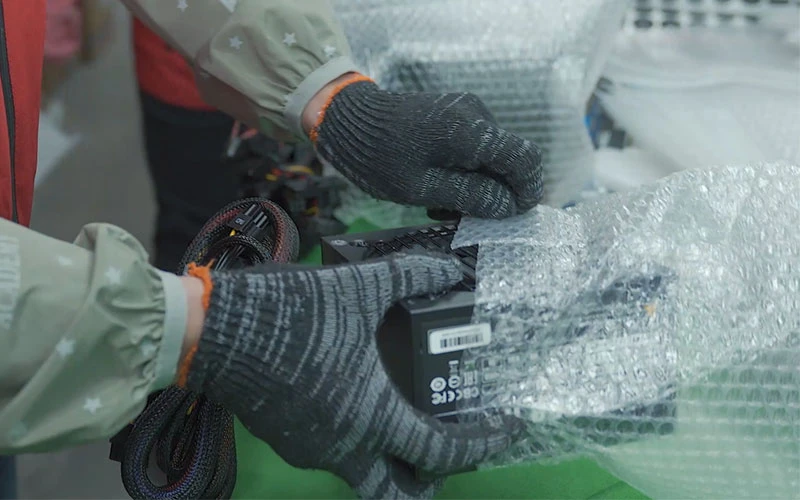
9. Packaging and shipment
Appearance inspection: clean the casing and check for scratches or assembly defects.
Accessory packaging: power cord, screws, manual, etc. are included.
Barcode and traceability: SN serial number label is attached for easy quality traceability.
Key quality control points
The above are the 9 steps to producing a benchtop power supply. In addition, there are the following points that need attention:
Capacitor life: Select high-quality Japanese or Taiwanese capacitors (such as Rubycon, Nippon Chemi-Con).
Heat dissipation design: Balance fan speed and noise to ensure long-term temperature control.
Welding quality: Avoid poor contact caused by false soldering and cold soldering.
Industry trends
Miniaturization and high power density: such as SFX power supply adapts to small host.
Digital control: Use digital signal processor (DSP) to achieve intelligent voltage regulation.
Fully modular design: Users can customize cables to reduce clutter in the chassis.
Through the above process, desktop power supplies must undergo strict process control and testing from design to finished product to ensure its reliability, efficiency and safety. Different brands may differ in materials (such as all-Japanese capacitors), degree of automation (such as all-robot SMT production lines) and testing standards.